A mobile instrument cart can hold its payload on a level floor and still twist when one caster hits a threshold. If the instrument relies on precise alignment, even a small shift at its mounting points can matter. Here’s what to check when considering carbon fiber for a medical equipment bracket, mobile platform, or support frame.
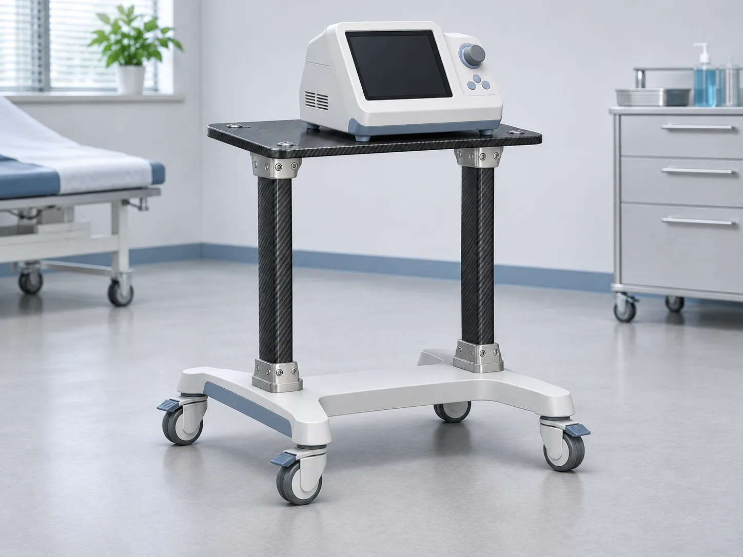
Concept illustration of a mobile instrument cart with carbon fiber uprights, a mounting plate, and metal end fittings.
Yes. Carbon fiber load-bearing components can support instruments and other equipment when the section, laminate, and joints are designed for the loads they will see in service. Common candidates include instrument brackets, mounting plates, and lightweight support frames.
Start by tracing the load from the equipment through its mounts and into the base. On a cart, an instrument placed off-center can put more load into one upright than the other. On a fixed bracket, an adjustable arm can create its highest bending load when fully extended. Both conditions are worth identifying before choosing a tube size or plate thickness.
Set an allowable deflection or rotation at the point where movement affects the equipment. For example, if two mounts hold a sensor in alignment, measure how far those mounts move relative to each other. Measuring deflection at the middle of the frame may miss that change.
For a mobile platform, include the expected payload, its center of gravity, and loads from representative stops and threshold crossings. Use the intended base and hardware when measuring movement. The way a frame is attached can affect the result as much as the stiffness of an individual tube or plate.
Fibers running along a tube contribute to bending stiffness. Angled plies help carry shear when the tube twists. The tube ends may need a different reinforcement strategy from the middle because fittings, clamps, and bolts introduce loads over a smaller area. If you’re designing an upright, review its section, layup, and end fittings together. Explore custom carbon fiber tubes
For a flat mounting plate, check the distance between supports and where holes or cutouts interrupt the laminate. A large cable opening next to a mounting hole can leave very little material to carry the load. Moving the opening or adding support under the plate may be more practical than increasing its thickness. Explore custom carbon fiber sheets
Yes, if the connection is designed for the laminate and the forces it carries. Check how the bolt bears against the hole, how much material remains between the hole and the edge, and how tightening the fastener compresses the laminate. A metal bushing or insert can provide a durable contact surface where hardware is regularly removed and reinstalled.
If the design uses a bonded metal fitting instead, specify the overlap and surface preparation. Check whether bending puts a peel load on either end of the bond.
Call out the features that control fit and alignment. If a plate bolts onto two end fittings, show how the hole pattern is located relative to the surfaces that seat on those fittings. Include inspection datums and the acceptable edge condition around holes and cutouts. If the assembled instrument needs two mounting faces to line up, specify how that alignment will be checked after assembly.
Test carbon fiber load-bearing components with their intended fasteners, fittings, and mounting conditions. Measure movement at the instrument mounts and check for joint slip, loosening, or permanent deformation after representative loading. If the assembly will be cleaned frequently, consider how the intended disinfectants may affect the laminate, finish, or bonded joints. For patient-support applications, the equipment manufacturer should establish the applicable requirements and verify the complete device for its intended use.
For custom carbon fiber medical parts, send the information that defines how the part will fit, carry load, and be inspected.
Drawings and models — 2D drawings, 3D files, mounting locations, and mating parts.
Loads and stiffness — Payload, load directions, offsets, expected cycles, and allowable movement.
Joints and tolerances — Fastener or insert details, inspection datums, and critical dimensions.
Environment and quantities — Cleaning agents, operating conditions, prototype quantity, and estimated production volume.
GBTECH can review these inputs to assess which parts are suited to custom tubes, CNC-machined plates, or a composite assembly with metal fittings. Send your drawings for a manufacturing review and quote
GBTECH U.S. Sales & Support
Website: www.gbtechmaterials.com
Email: zane@gbtechgroup.cn
Phone: +1 (510) 902-9987
California Warehouse: 38758 Buckboard Common, Fremont, CA 94536, United States
China Manufacturing Headquarters: Building 1, Left Side, Tangye Road, Xinxu, Huiyang, Huizhou, China
Selected standard products are stocked in California. Contact us to confirm availability, shipping origin and lead time for your specifications.


 WhatsApp
 E-mail