When a medical imaging table extends into the scanner bore, the section furthest from the base is often where deflection matters most. The tabletop may carry the intended load and still sag enough to affect patient position or equipment clearance. A thicker carbon fiber patient support panel can improve stiffness, but it can also put more material in the beam path. The equipment team needs to look at the loading, allowable movement, and imaging field together before settling on a panel thickness.
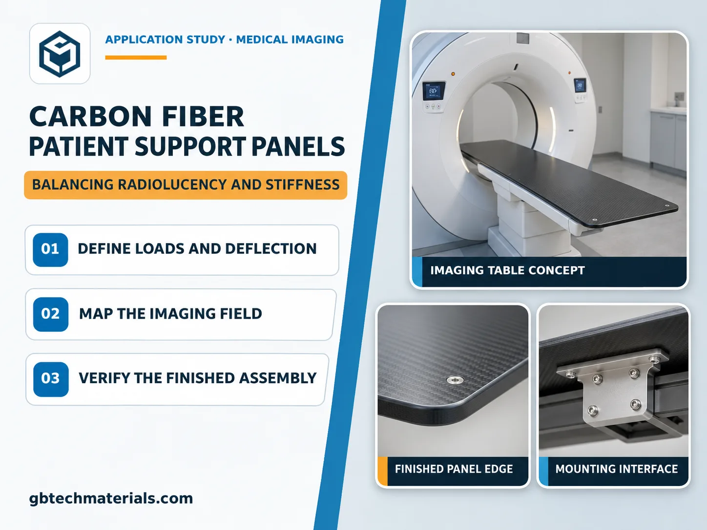
Concept illustration of a medical imaging table, with details of the panel edge and mounting interface.
Consider a tabletop that slides forward from a base into a scanner. The same load produces different bending effects depending on how far it sits from the support. A load toward one side can also twist the panel. Define the travel range, support locations, intended patient and accessory loads, and the points where deflection will be measured. For an extended tabletop, displacement and tilt near the imaging region may matter more than movement next to the base.
Include the mounting structure when evaluating a carbon fiber patient support panel. A panel clamped to a rigid test fixture may give a different result once installed on a base that can also deflect. A representative fixture can help compare early concepts. Check the final deflection with the production mounting interfaces in place.
Fibers along the tabletop can help resist longitudinal bending. Other ply angles can be used to address transverse loads and twisting. For a longer span, the OEM may also consider a sandwich panel. Separating the faces can improve bending stiffness, while the core and bond lines must be included wherever the beam passes through them.
Mark the usable field and intended beam angles on the assembly drawing. Then check where reinforcements, inserts, and fasteners sit relative to that field. Moving a metal fitting beyond the imaging area may leave more freedom to design the joint. If the fitting must stay within the field, assess its effect in the finished assembly. When comparing carbon fiber sheets for a radiolucent composite panel, check both the overall transmission and how it varies across the usable field. Two panels with similar average readings can show different local patterns.
Choose the finish with the equipment’s cleaning and disinfection routine in mind. Define the coating, edge sealing, and expected exposure before approving the sample. If a coating or bonded layer sits in the imaging field, include it in the test sample so the team evaluates the same construction that will go into the device.
On the machining drawing, tie the hole positions, locating surfaces, and flatness requirements to the way the tabletop mounts. If the hole pattern is off, the installer may have to pull the panel into place with the fasteners, changing its starting shape. On the first assembly, check that the panel seats against the intended surfaces, the hardware fits, and the tabletop clears the equipment throughout its travel.
The equipment manufacturer should determine the applicable requirements for the device’s intended use and target markets, then carry out the corresponding testing and compliance verification on a representative final configuration. For structural checks, define the loads, table positions, and operating conditions to be evaluated. For imaging checks, use the intended beam conditions and review transmission, uniformity, and any visible artifacts near reinforcements or joints.
A coupon can help compare materials early. It cannot reproduce every feature of a full carbon fiber patient support panel, particularly where a local thickness change or a fitting enters the imaging field. Test those areas with the layers and attachments in place.
If you are evaluating a panel for a medical imaging table, include the assembly drawing, load distribution, travel range, deflection limits, usable imaging field, and cleaning conditions when you send your drawings to GBTECH for a manufacturing review. Mark the mating surfaces and any features that must stay within the field. Those details help define the scope for panel supply, CNC machining, edge finishing, and first-part inspection.
GBTECH U.S. Sales & Support
Website: www.gbtechmaterials.com
Email: zane@gbtechgroup.cn
Phone: +1 (510) 902-9987
California Warehouse: 38758 Buckboard Common, Fremont, CA 94536, United States
China Manufacturing Headquarters: Building 1, Left Side, Tangye Road, Xinxu, Huiyang, Huizhou, China
Selected standard products are stocked in California. Contact us to confirm availability, shipping origin and lead time for your specifications.


 WhatsApp
 E-mail