A medical equipment OEM may already know where a diagnostic module needs to sit inside an enclosure. The base hole pattern is fixed, the cable harness needs a route through the mounting plate, and a technician must be able to reach the fasteners. Each part can look straightforward on its own drawing. Put them together, though, and a bolt directly above a frame rail can leave too little room for a wrench.
For custom carbon fiber medical parts, reviewing the assembly before machining gives the OEM and supplier time to resolve those details while the tube lengths, plate geometry, and metal fittings can still be changed.
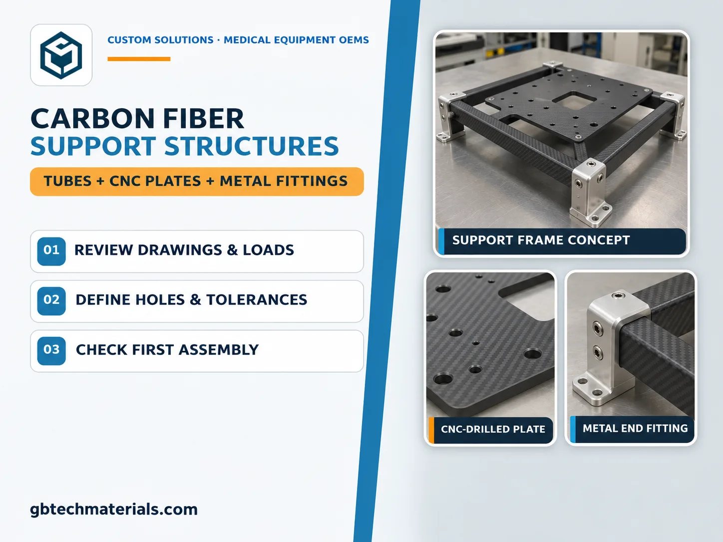
Start with the equipment weight, center of gravity, and mounting points. If the module sits closer to one side of the frame, the two rails may carry different loads. If it stays installed during transport, include the expected transport loads. Where the instrument depends on alignment, specify how much movement is acceptable at its mounts and where that movement should be measured.
The assembly drawing should also show which dimensions are fixed by existing hardware. The base hole pattern may be fixed, while a cable opening can move slightly to leave more material around a nearby mounting hole. For equipment that is cleaned regularly, provide the cleaning agents and expected exposure so the supplier can review the finish, exposed edges, and joint materials together.
A carbon fiber support frame can use two rails to span the enclosure and a machined plate to carry the module. When specifying custom carbon fiber tubes for the rails, start with the unsupported span and the position of the module. An off-center load can twist the frame as well as bend the rails, so the tube section, layup, and end fittings should be reviewed together.
A mounting plate machined from carbon fiber sheet can incorporate holes, slots, and cable openings in a single part. Check the underside of the plate in the assembly model before releasing the drawing. A mounting hole may line up with the instrument and still leave too little room for a washer underneath. Where the assembly needs to come apart for servicing, a metal fitting can provide a threaded interface for repeated use.
Separate the features that locate the equipment from those that provide clearance. If two dowels locate the module and four bolts hold it down, specify the dowel hole positions from the surfaces used to locate the module. The bolt holes need enough clearance for the fasteners to pass through once the module is seated. Give the supplier the required diameters, positions, and seating details for both sets of holes.
For carbon fiber CNC machining, agree on the acceptable edge condition around drilled holes and cutouts. The setup should support the laminate where the drill exits and hold the plate without forcing it flat. If a hole pattern spans several parts, decide whether those parts can be machined separately from common datums or whether the pattern needs to be finished after assembly.
Individual parts can pass inspection while the installed module still rocks on its mounting faces. Small differences in plate flatness, fitting height, and rail position can add up. For custom carbon fiber medical parts, agree early on which dimensions to inspect on each component and which to measure on the assembled frame.
Fit the first frame to the intended base and install the module with the actual hardware. Check that the fasteners seat fully, a tool can reach each bolt, and the connectors clear the plate. Run through the planned service sequence as well. If the module cannot be removed without taking out a rail, revise the layout before machining the next batch.
Put together the latest assembly drawing and the requirements that affect manufacturing and fit.
Drawings and interfaces — 2D drawings, 3D models, mounting points, and mating hardware.
Loads and operating conditions — Payload, center of gravity, allowable movement, and cleaning exposure.
Machining and inspection — Hole patterns, critical tolerances, datums, and assembly checks.
Order scope — Prototype and production quantities, plus whether you need individual parts, a matched kit, or an assembled frame.
If a hole pattern or fitting dimension is still open, mark it on the current drawing before you send it to GBTECH for review. With the mating parts and load conditions in view, we can discuss which features to machine into the composite and which to put in the metal fittings.
GBTECH U.S. Sales & Support
Website: www.gbtechmaterials.com
Email: zane@gbtechgroup.cn
Phone: +1 (510) 902-9987
California Warehouse: 38758 Buckboard Common, Fremont, CA 94536, United States
China Manufacturing Headquarters: Building 1, Left Side, Tangye Road, Xinxu, Huiyang, Huizhou, China
Selected standard products are stocked in California. Contact us to confirm availability, shipping origin and lead time for your specifications.


 WhatsApp
 E-mail