Two carbon fiber panels with the same nominal thickness can give different detector readings on the same X-ray system. Even when their average transmission is similar, one panel may show a band or patch where more of the beam is attenuated. For an imaging equipment manufacturer, those are two separate checks. Carbon fiber X-ray transparency depends on how much material the beam passes through, what that material contains, and how evenly it is distributed across the imaging area.
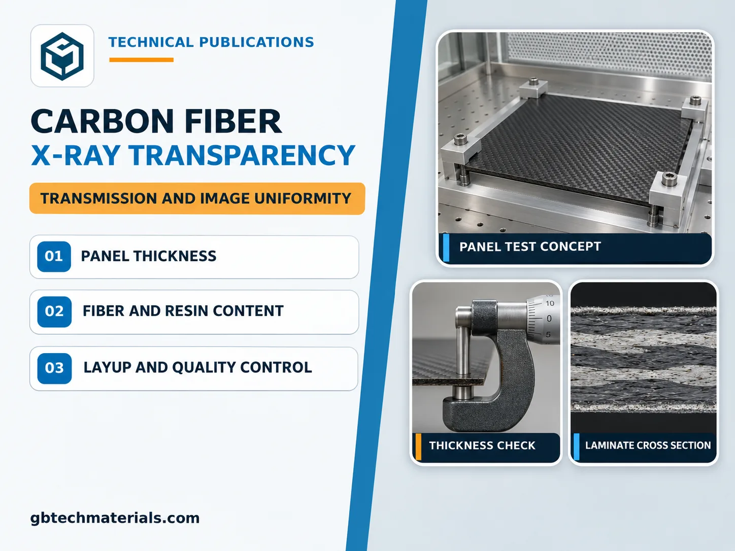
For the same laminate and beam conditions, a thicker section attenuates more of the primary beam. The beam path also gets longer when it crosses a flat panel at an angle. If the equipment acquires images from several positions, a measurement taken with the beam perpendicular to the panel describes only one of those positions.
When specifying carbon fiber sheets for an imaging panel, mark the usable imaging area on the drawing. A nominal thickness and a few readings around the perimeter may miss a thicker strip across the middle. A thickness map gives the supplier and the equipment team a common reference when comparing a dimensional change with a change in detector signal.
Fiber volume fraction tells you how much of the laminate volume is occupied by fibers. At the same finished thickness, changing that fraction changes the proportions of fiber and resin and can change the panel’s mass per unit area. X-ray attenuation depends on that mass, the material’s elemental composition, and the photon energy. A higher fiber volume fraction, by itself, gives too little information to predict whether transmission will rise or fall.
The resin formulation matters too. If a supplier changes to a filled resin or adds a coating, include that change in the evaluation. For an initial comparison of carbon fiber X-ray transparency, ask for the finished thickness, mass per unit area, fiber and resin system, and any fillers, coatings, or adhesive layers in the beam path. Two panels described as radiolucent carbon fiber may differ on several of those points.
Ply orientation is usually chosen for stiffness and load transfer. For imaging, also review how the plies are distributed across the usable field. A ply overlap, reinforcement patch, or transition where plies terminate can add material locally. In a sandwich panel, the core and adhesive layers are also part of the beam path. A coupon cut from a uniform region may miss those features entirely.
Map the imaging field against the layup and assembly drawings before releasing the design. If a joint, insert, or reinforcement must cross that field, include it in the full-panel test. This is especially useful when a prototype coupon has passed and the production drawing adds hardware or edge reinforcement.
Thickness can vary with ply placement, consolidation, and resin flow. Resin-rich zones, voids, and inclusions can also change local material distribution. Whether a defect leaves a visible mark depends on its size, location, and the imaging setup. Some defects can affect structural performance even when the transmission map shows little change.
For carbon fiber imaging panels, agree on where thickness will be measured and which regions need internal inspection. Where appropriate, a qualified ultrasonic inspection can help assess internal laminate quality. Use the X-ray test to check transmission and image uniformity under the intended beam conditions. Compare the results of each inspection with its own acceptance criteria.
To compare carbon fiber X-ray transparency across samples, record the tube voltage, filtration, geometry, detector settings, and the region measured. Under matched conditions, compare a reference exposure taken without the panel with an exposure taken through the finished panel. Review both the average signal and its variation across the usable field. If a band appears, check whether it lines up with a thickness change, a ply overlap, or a reinforcement patch before attributing it to the resin or fiber.
For a manufacturing review, share the panel drawing, imaging field, thickness limits, structural requirements, and the beam conditions and acceptance criteria your team uses. Flag any coatings, bonded layers, or hardware within the field. If the panel is still at the prototype stage, you can send the current drawing to GBTECH for review to discuss the layup, machining, and inspection before the first build.
GBTECH U.S. Sales & Support
Website: www.gbtechmaterials.com
Email: zane@gbtechgroup.cn
Phone: +1 (510) 902-9987
California Warehouse: 38758 Buckboard Common, Fremont, CA 94536, United States
China Manufacturing Headquarters: Building 1, Left Side, Tangye Road, Xinxu, Huiyang, Huizhou, China
Selected standard products are stocked in California. Contact us to confirm availability, shipping origin and lead time for your specifications.


 WhatsApp
 E-mail